Sunday, March 25, 2012

Dual tiller extensions and ISAF offshore special regulations

I started making one tiller extension early December. After adding unidirectional manually to the PVC core, I was happy with the weight and stiffness but had a bad feeling regarding toughness.  I decided to add bidirectional for durability and increased ultimate stiffness/less delaminating risk.So I decided to buy sleeves from Soller composites as I had good experience with this product from the bow pole and rudder/daggerbosrd builds.  I had terrible experience with their special treated heat shrinking tubing for the bow pole, but decided to give the muck thinner 0.79" tube a go.  I noticed special instructions for the use of the thickest tube had been added, wise!

The one extension already laminated with UD got a treat with the sanding paper, then I threaded the 1" bi directional sleeve outside and added liberal amounts of epoxy.  Then the heat shrinking tube was threaded over it all and heated from the center out each direction with a heat gun. Smooth process.

As I planned for a one step lamination, I was a bit more sceptical about the next one and got an extra set of hands for parts of this process.  First, after roughing up the PVC with sanding paper, I added two layers of UD using spray glue to keep it in place.  Then taped each end to keep it from frying.  Bidirectional sleeve was applied over this and really liberal amounts of epoxy was added.  Then the heat shrinking tube the same way as described above.  When heating the tube, the epoxy also gets heated, obviously, and this first makes it very low viscosity (, then it gels).  So when you see epoxy running out under the heat shrinking tube each end this is a sign that all the carbon is most likely well saturated.  This was the case here.

After curing I cut the heat shrinking tube and removed it uneventfully to reveal these two tubes:


Being weighed, untrimmed, without hardware, the two three meter tubes came in at 878 grams total.


Finally, I added rubber links with detachable tiller fitting.


Then we have the ISAF OFFSHORE SPECIAL REGULATIONS, and this rule comes in to play:
3.14.4 Special Requirements for Pulpits, Stanchions, Lifelines on
Multihulls

Mu0,1,2,3,4
The following shall be provided:-
....
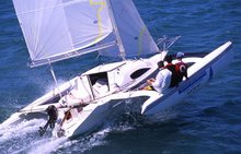
c) on a trimaran - at a main or emergency steering position on an outrigger
with or without a cockpit, lifelines protecting an arc of 3 meters diameter
centred on the steering position. (When measuring between lifelines their
Mu0,1,2,3,4
taut, undeflected positions shall be taken for this purpose).


There is no way I'm going to put up 450 mm high stanchions with lifeline around the floats, so these tiller extensions have to be left at home when racing under ISAF regulations.  That is why I have ordered art 104017 on this page: It will allow steering from the net but not "on an outrigger with or without a cockpit..."


Another comply with the rules thing now almost done, I test fitted the newly rebuilt and re painted pop top today, complying, well adjustments and deviation card still left, with this rule


3.24 Compass
3.24.1 The following shall be provided:-
a) a marine magnetic compass, independent of any power supply,
permanently installed and correctly adjusted with deviation card

(I would fit a compass regardless of the rules)

Wednesday, March 21, 2012

Battery stand. Holding tank.

It was about time to decide on where to put the battery.  So I did yesterday.  The 6,3 kg 30Ah LiFePO4 battery, containing about the same usable energy as a 20+ kg 60 Ah lead-acid battery, will sit under the forward port corner of the cockpit.  I have made a stand ready to glue in place from scrap panels:


First I bogged the parts together and kept them in position with temporary screws and a foam wedge.  Then I taped it all together and covered exposed edges. I will use a webbing around the battery and the cross member behind it to keep it secured in place.  Right side of the stand in the picture will be glued and taped to the aft face of the main bulkhead.


I started the making of the holding tank last year, as the holding tank supplied with the Raske en van der Meyde light weight bayonet catch marine toilet unfortunately proved to be just a tiny tad too big for the 22.  Today I continued the preparations of the holding tank top/toilet stand.

Seen in this picture is the one side laminated and contoured holding tank top as made last year.  I marked the positions for the toilet fastening bolts and the tank inlet, cut the foam and replaced with HD foam.  Hex bolts were countersunk and epoxied in to the HD from the underside before fitting the pieces. I just now, as I was writing this, realised that I forgot to put HD foam in for the venting trough top fitting.  Damned!


Then the top was laminated with 200gsm 0/90 carbon fibre. From the (probably) same in comprehensive reason this picture is also mirrored. In front one can see part of one of the tiller extensions wrapped in Soller Composite's special treated heat shrink tube.

Engine mount modifications. Tiller - engine connection

Sea trials revealed several less than perfect aspects with the engine mount.  The mounting bracket interfered with the engine when tilting, making both hard to operate.  The engine tilt lock was difficult to access tilted or not.  The engine was not able to tilt all the way down to vertical.  The control cables had tight operational condition.  I decided to rebuild the engine mounting plate to overcome these issues.  Made in plywood for now, maybe a lightweight and resistant to the environment version will be built later.

First I epoxied 8mm plywood strips between the mounting bracket and the engine mounting plate


Then I added wedges of wood, epoxied to the mounting plate, on the aft side to tilt the engine a bit down, and further move the upper part aft in order to gain access to the tilt lock. (For some reason, beyond my comprehension, this is a mirror image)


These two steps made the operation of the engine much easier.  Now time for steering link.  I have drawn inspiration from pictures uploaded by members of the Yahoo F-boats forum.  By the way, there is now a new, uncensored F-boat forum started by Ian Farrier as well.  However, as I have to go to the swim step to lower and start the engine anyway I didn't see any advantage in a remote operated steering link and thus have made it as simple as possible.

I used a low stretch line from a hole in the engine trough a piece of PVC tube and to a horn cleat mounted on the tiller.  The line was too thin for the hole in the engine and this created an unacceptable amount of play in the system.


So I used a second piece of the same rope, inserted it to the original rope and thus had two ends to make a nice diamond knot at the engine end as well as taking out the play in the hole.
Those familiar to Yamahas will also see the tilt lock now clear of the bracket control.


When a connection between tiller and outboard is desired, the rope is tightened and fastened at the horn cleat


And a relatively tight and stable connection is made.


Then, when the connection is not desired, it is easily left free by uncleating the rope. The PVC tube will just hang free and does not interfere with tiller operation

Tuesday, March 20, 2012

Finishing mast

I had to hire help with special qualifications in order to get the Nexus MRC unit (mast rotation compensation) in to the mast. My son Eilert fixed that very well. It is attached with Velcro strips glued to the internal athwartships web and the unit. Eilert at work:


The MRC unit in place:


Network cable coming from the mast head wind sensor, going trough the MRC unit and further to the gooseneck into the boat along with the VHF antenna.


The mast rigged and ready to leave the chicken house


Now hanging in the barn ready to be lowered on to the boat again

Tuesday, March 06, 2012

Halyards and utterly off topic

I borrowed some equipment from my electrician friend and was no way near to succeed in treading the halyards. A couple of days later I brought Guttorm and we succeeded after some initial trying and failing.  The now established and proven method of treading halyards on this kind of mast is:
1. Tread a 6+ m long steel hydraulic tube up the mast trough the desired bottom halyard exit
2. After removing the top cap, place a 500W lamp at the mast top to lighten the interior of the mast.
3. Place one halyard treader at the bottom of the mast and one halyard fisher at the desired upper halyard exit.
4.  Tread an electricians "wire treading tool" up the hydraulic tube, carefully inspect the inside of the mast and fish it out the exit.

This proved to be quite fast and easy after the technique was "polished" a bit, and we now hope that the different halyards do not interfere with each other more than absolutely necessary.

It is also going to work out with the fluorescent paint thanks to one of my new friends trough this blog, Mr Guy Waites.  Thank You!

And now to something far off topic.  I'm in the process of reassembling my commuting tool after some "minor" engine modifications,


And of course a bit of a paint job in order to match it better with the boat.