Saturday, April 26, 2008

Cleaning up. Abstract on mast discussions

It was over due for a thorough clean up in the workshop today (see pictures from the few previous posts). Eivind picked up the centerboard yesterday evening and will probably mount it this weekend. I'm anxious to try it out, I expect a noticeable difference in upwind performance. I also discovered a major defect in the melamine table surface, probably due to the vacuum lifting it off the table when bagging the centerboard and not being able to let the bag follow the table all the way. I have not decided on how to address this problem yet.


I placed a question regarding the effects of choosing a larger wing mast profile (large aerodynamic section, no spreaders) on the discussion forum of the Norwegian Multihull Association. I got a few extensive inputs from sailors and designers of former world championship campaigning boats. Summary:

Topics to be considered:
- Total weight
- Aerodynamic qualities
- Parasitic drag
- Functionality

Possible mast choices:
- True wing profile
- Small regular "wing" profile rotating mast with diamond spreaders
- Non rotating mast

Advantages on Wing mast design (e.g. Lege Cap Ferret, Mirage)
- Superior aerodynamic properties, a lot more power (reaching effectiveness)
- Dramatically less parasitic drag (upwind effectiveness)
- Functionality. It will withstand the sail forces very well including reefed main and large masthead spinnaker. Less drag on trailer. No spreader/headsail interference.

Disadvantages:
-Weight. Probably marginal differences in total weight (including running and staying rigging) assuming correct engineering (with a shear web), high quality fibers and quality workmanship.
- Cost and work required.

Advantages on a non rotating rig:
- Weight. Lightest of the three.
- Functionality. Standing rigging giving the reqired support, safe reefing.
- Low cost, easy availabe.

Comments on the smaller (standard) rotating profiles:
- Too small profile to be really aerodynamic efficient, better than non rotating though.
- Difficulties due to spreader/headsail interference, prohibiting sufficient rotation, leading to extensive side forces on the mast top.
- Not enough stiffness when reefing, this can easier be overcome by a babystay on a non rotating mast.
- Heavier than you like to believe

Friday, April 25, 2008

Challenges when not using vacuum - bubble trouble part II

On my recent 40th birthday my soon 5 years old son gave me this masterpiece to be kept in the workshop. It's a boat and a dangerous rock in a red ocean (acryl on canvas). Tusen takk, Eilert!


As covered in an earlier post I ran in to problems with the vacuum integrity when trying to infuse the outer hull skins and kind of gave it all up, converting to hand lay up for the float outer skins. It is, however, not so sure you can get away with this method without trouble either, at least I didn't (nor did Jay).

I've been trying not to think about it, hoping this would fix the problem. Unfortunately, this head in the sand approach didn't lead to any solution, and now this is the only float side not faired and I had to face the problem.

With glass it is usually very obvious where an air bubble in the laminate is (clearly visible), but with these un-see-through fibers I use it is harder. I put up a lot of lightsources and used my hand to localize the bubbles, then marked them with a marker. I found a few more later on, even though I went over the whole float quite thoroughly.


Bow view. Close to 30 bubbles all together....


I started in the aft part, using a 30.000 rpm grinder with 50 grit paper (aramid (Kevlar®) is definately resistant to mechanical wear) and worked my way in until I met the foam core. Tapering off the circumference and laminating a layer of hybrid covered with a bigger piece of carbon as the carbon cloth is thinner and I suspected this would give a smoother transition between the repair and the hull. I took no chances this time and let it cure under vacuum.


It turned out the vacuum was very effective in minimizing the bumps from overlapping and I continued with the rest (and more visible parts) of the float inner side using the same approach.
Close up of one of the patches:


It actually looks like the float caught some kind of nasty disease....


The rest of the lesions under cure:


Healed!!!

Finishing centerboard for Frimann

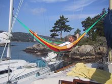
By the way, in the "Summer in Norway" picture to the right I am hanging from Frimann and the Avance 24 "Ocean Explorer IV" at Gråøya in the Oslo Fjord.

Fairing the board. Focus on the foil section. The rest of the board just for filling the glass structure.


When clamped to the end of the table it is possible to add a new layer of fairing compound to both sides in one operation.


After (fast and slightly) fairing the board was epoxy coated using roll and tip technique.


Some imperfections revealed with shiny surface but I decided it was good enough.


Then I made a "paint box" in the workshop. I bolted wooden stringers to the ceiling and stapled a plastic film to this hanging all the way down to the floor. Three walls like this and using the concrete wall as the fourth one. Then a "forensic suit" and carbon filter mask.


By hanging the board from three hooks in the ceiling the board hung quite steady and was accessible from all sides.


After a quick run with 360 grit wet paper the "Biltema" LPU paint was applied using a regular compressed air paint gun (5 lbs). I have very little experience with this kind of equipment and none with LPU paint and this painting session is to be regarded as a testing/training session, this implies I had to add paint until running to find out how thick layers it is not possible to apply....


The foil section ended up remarkably nice though.


And last, the leading edge.

Monday, April 14, 2008

Centerboard and masts

Second side of the centerboard glassed. Moving towards F-boat building...


I really appreciated the comments on the last posting, Silas and Martin! I think the language have made it difficult for me to express my self precise regarding the possible mast building plans, here are answers to your comments. Feel free to argue with me, I would appreciate it!

I do not intend to make the rig in other dimensions than specified, i.e. 10,7m mast (35'1") except for the dimension of the spar that is. Thus I will not need the middle section of the moulds and the thickest part will be somewhat smaller than the dimensions of the mould, but still considerably larger than the Marstöm spar (or the guidelines from the designer) and it will have to be as there are no spreaders.
I guess, however, that the spar should not be symmetrical but rather with the thickest part at the specified position for the spreaders, and thus the mast top will be the dimensions at the smallest end of the mould and the bottom somewhat larger.
As I am not an engineer I will have to pay someone to do some calculations on the required laminate thickness in order to achieve adequate strength. If it turns out that this makes the spar considerably heavier than the specified section it's a no go, I totally agree that weight aloft is not a good solution. I will save weight and drag in not having spreaders and diamond wires with corresponding attachment points for these, however.
It is quite a stick, but I don't see how it is too big if it is not too heavy? It will contribute to about 4 m^2 of sail plan though. And it will be more of a true "wing mast" rather than a low drag mast.
The Marström mast is certainly a nice one and costs probably around Euro 8.900,- plus taxes (in my case at least 25%) everything but halyards and forestay included.

A few more pictures of the moulds, made from GRP with ply reinforcements:

And gelcoat on the inside which needs some minor repairs


It is designed to have a center web lying across the section to pick up the forces trying to bend the section sideways.

Wednesday, April 09, 2008

More on Telstar replacement centerboard and a bit of carbon wing mast planning

The ply/ss/foam centerboard tended to twist, that's why I decided to glass and bag one side at a time and " strap" the board against the table with vacuum while curing. This worked OK. I unwrapped today and it is now less twisted. It is, however, remarkable how stiff carbon is. I would expect the board to be stiffer with 200g carbon than it seems with 450g glass.

This is how the new board looks like in the correct orientation. The original had the curved part out on the right in this picture extending down to less than a foot from the bottom, leaving a lot of ineffective wetted surface. That's why, long before I decided to build a Farrier design, I started to plan a new board when I would find the time for it. I didn't, but finally had to..... Guess I need a new rudder as well quite soon.

Detail of the not-as-sophisticated-as-the-Farrier-boards Telstar replacement board. In stead of unidirectional carbon an ss reinforcement is rebated down each side, bolted and welded together. Guess it won't break in a breeze again. The several layers of ply and ss is wrapped in one layer of 450g 45/45 glass.

Eivind decided on the profile, and made the board, finishing and glassing left for me to do. I think it is a NACA 0012 profile. This is what it looks like anyway. The original board was a big rectangular underwater break.

I also borrowed Eivind's mast moulds. This mast was originally designed for the Mirage formula 28 trimaran and they are thus 7,5 m long, each one making one fourth of the mast. The mast is then 15m (49,2 ft), symmetrical around the mid point. It is (if you haven't already noticed on the above link) quite a bit bigger in the middle section and it does not carry spreaders or diamonds. If I decide to build from these moulds (the alternative is to buy a Marström mast) I guess I will place the fatter part at the spreader position, not at the center of the mast. And I will have to get someone do some calculations for me. I plan to make the mast foot an integrated part of the carbon construction. It is however tempting to go with the Martröm, details of such a mast made for a bigger F-boat here.

This is the middle section end of the moulds, measuring approximately 23 cm x 52 cm (9" x 20 1/2")

This is the top and bottom, approximately 10 cm x 29 cm (4 x 11 1/2")


I will be going on a short vacation, hopefully I will be able to finish the board laminations on Sunday evening and get on with the F-22 again.

Seat tops and Telstar centerboard

It has not been much time available for boat building lately. However, I released, with some struggle, the seat tops from the table and they are now roughly cut to shape from plan drawings. They are indeed very stiff!

Starboard seat top seen from "boat center". This is the small center cockpit due to full cabin and aft cabin version, chosen for cruising on N 63°

Laminating and bagging the upgrade centerboard for Frimann, my old Telstar 26 Trimaran. I have been thinking about making a new centerboard, as the old one was a plain plywood board with lots of wetted surface and no lift, but it had to break before I got to it...

I am also preparing the port float for fairing.