First, I should emphasis that this mast is not a part of the Ian Farrier supplied design for this boat, and I must personally take full responsibility for its suitability and durability. And as I am a surgeon rather than an engineer, I have little basis for calculating the optimal way of building it for this vessel, or any other. It is based on "reversed engineering", trying to get it as sturdy as possible while not exceeding a maximum acceptable weight. Time will tell if I succeed.
It has been a while now since I made any serious infusion setups. Even though it is a lot of work, the thought struck me this evening when I was fitting the bag, listening to "sløyt og drøyt" (a music show that translates to something like far out and funky) on the radio that this is indeed a very 'cozy' way to make composite parts, as opposed to the vacuum bagging of wet lay ups that I have done mostly for a while now. Not every job is suitable for infusion of course, but when it is, it not only provides you a supreme quality part, it also relieves the stress and makes the anxiety of not getting the bag on in time or epoxy spilling on the tape and so on redundant. It was somewhere were this picture was taken that these thoughts struck me.

Even though all the building materials were fitted earlier today, it was still a whole lot to cut and get in the right place. Peel ply, then the perforated release film. Then I added a double layer resin distribution media (RDM), shown as the blue net in the pictures. In close conjunction to that I put the epoxy feeder line, led in at the lowest part of the mould. I'm using a cable collector from "Biltema" as in-bag distributor. Due to the shape of this part there are two high sides and hence two suctions are needed, shown in the above photo where exiting the bag at the highest point. After I got all these things in, I had to complete the mould by adding the two T-bars, the pictures showing the starboard one in place, the port about to be fitted. The below picture at the same stage, showing the opposite side of the bag. You can see the feeding tube entering the bag at the lowest point.

Finally, the vacuum bag can be fitted. Astonishingly, it had no leaks when I started the pump. However, it was not long until I heard a snap and a hole was created close to the feeding tube entry. A patch was added as shown.

Then I mixed up 4,5 kg of SP system Prime 20 LV infusion system epoxy. I'm not used to this kind of quite heavy lay ups, the laminate here being about 2,5 times heavier than the beam bulkhead lay up of the boat. So I spent some time making up additional batches until at last 8,4 kg in total was infused. This means undoubtedly that I have to order more of the infusion epoxy. What is not yet so clear is whether the mast is going to be much heavier than calculated. A lot of this epoxy is spilled, for instance three 4,5m feeding/suction tubes (around 1000 ccm) and all that is still kept in the RDM. I expect to find some in the resin trap tomorrow as well. It is approximately 5,8 kg of carbon in this piece, so the optimal amount of epoxy would be about half of that plus what is needed to saturate the foam surface and fill the perforations.

Just opened for the epoxy. It started bubblibg just inside the bag, indicating something was terrible wrong. The vacuum fell less than 0,05 Bar, but the vacuum is not that interesting when air is introduced along with the epoxy. i was not able to hear a leak, just the bubbling from the feeding tube. The epoxy flowed in at a usual rate, but it was distributed unusually as shown below. It was obviously distributed quite normal along the mould and back trough the perforations, but mostly air was distributed in the RDM. You can also see the feeding line full of air (2% air that is, from the colour of it). This would make a dry laminate and the leak had to be defeated!
Finally I succeeded (don't know how as I never found the leak, it just stopped bubbling) and the piece was fully saturated.
On this last picture you can see the excess carbon without RDM along it extending from the glueing flanges and still saturated. The suction lines starting to fill with resin after the inlet had been closed. It will undoubtedly be another high quality composite piece.
I stopped the pump and the bag kept a steady vacuum, excess resin slowly filling up the suction lines. I turned the temp up to 26
ºC and left trough the winter night to have a beer and write this story.


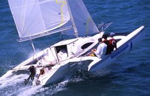

